
JONATHAN ERMAN | Fall 2021
Reprinted with permission from Simple Solutions That Work!
Download PDF: English
- You need to consider volume, modulus and location for successful risering practices
- Rigging castings manually is simple and generates good results
- Chemex Tele-Feeders should be considered for better yield, efficiency, and profitability
Exothermic and insulating feeding systems (or feeders) are common practice in our industry. With the development of modern high production molding equipment, we have accepted the challenges in developing feeding aids for these new systems.
Innovative rigging systems have also helped foundries improve productivity by increasing the number of castings per mold. Although this is a positive economic change, it limits positioning, sizing and feeder contact area on the pattern plate, making it challenging for the foundry engineer to produce shrink-free castings. Advancements in manufactured feeding aids are trying to meet the challenges foundries face by balancing improved processes, productivity demands and costs while maintaining high quality castings.
In the past, foundries operated with as low as a 30% yield, resulting in additional personnel requirements and higher after-cast processing costs. The pain point in many North American foundries today is the lack of manpower. By optimizing casting yield and having the ability to easily remove feeders from the casting, you can reduce cleaning time and handling of castings and returns, as well as ergonomic improvements. These improvements can result in reduced staffing requirements in the foundry after-cast operations. This is one of many ways that improved risering can improve the bottom line of a foundry business.
Few topics in foundry operation are equally as unique to our industry as the need to feed castings through the solidification of cast metals. Many terms are used to describe the products which supply the feed metal:
- Risers
- Feeders
- Feeding aids
- Riser heads
- Sleeves
The widespread growth and implementation of solidification software in our industry has improved optimizing feeder sizing, placement, and design. It has also given foundry personnel insights into how castings solidify as well as the parameters and criteria which lead to solid, defect-free castings. It’s hard to quantify the impact solidification software technology has had to our industry. Unfortunately, the available software packages can be costly and time consuming. That makes it unrealistic to do simulations for every casting in production or as a means to troubleshoot every casting issue. We can’t rely on solidification software alone. We need to make accurate feeding recommendations as timely and efficient as possible. The following process illustrates an alternative methodology to quickly achieve reliable results.
EXAMPLE: |
|
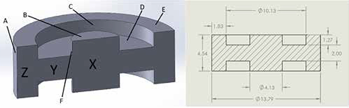
Calculation of Casting Modulus and Section Modulus for Hub Casting
| Surface | Equation | Surface Area |
|---|---|---|
| A | πDH | 3.141 x 13.79 x 4.54 = 196.65 in2 |
| B | πR^2 (2) | 3.141 x (2.065)2 x 2 = 26.79 in2 |
| C | πDH (2) | 3.141 x 10.13 x 1.27 x 2 = 80.82 in2 |
| D |
(πR^2-πR^2) (2) |
3.141 x (5.065)2 = 80.58 - 3.141 x (2.065)2 = 13.39 = 67.19 x 2 = 134.38 in2 |
| E |
(πR^2-πR^2) (2) |
3.141 x (6.895)2 = 149.33 - 3.141 x (5.065)2 = 80.58 = 68.75 x 2 = 137.50 in2 |
| F |
πDH (2) |
3.141 x 4.13 x 1.27 x 2 = 32.95 in2 Total Surface Area = 609.10 in2 |
| Section | Equation | Volume |
|---|---|---|
| X | πR^2 H | 3.141 x (2.065)2 x 4.54 = 60.81 in³ |
| Y |
πR^2 H-πR^2 H |
3.141 x (5.065)2 x 2 = 161.16 in3 - 3.141 x (2.065)2 x 2 = - 26.79 in3 134.37 in3 |
| Z |
πR^2 H-πR^2 H |
3.141 x (6.895)2 x 4.54 = 677.95 in3 - 3.141 x (5.065)2 x 4.54 = -365.83 in3 312.12 in3 |
Total Casting Modulus:
Volume/Cooling Surface Area = 507.30 in3/609.10 in2 = 0.833 in.
Modulus of Section X - Center Hub
Volume Section X / Cooling Surface Area of Section X
60.81/ (B+F) = 60.81/59.74 = M = 1.018 in.
Modulus of Section Y - Web
Volume Section Y / Cooling Surface Area of Section Y
134.37/D = 134.37/134.38 = M = 0.9999 in.
Modulus of Section Z - Outer Rim
Volume of Section Z / Cooling Surface Area of Section Z
312.12/ C+E+A = 312.12/ (80.82+137.50+196.65) = M = 0.752
VOLUME CONSIDERATION
The volume of the casting multiplied by the known volumetric shrinkage of a given alloy will tell you what amount of feed metal is required to generate a solid part. If the volumetric demand of the casting is not satisfied by the feeder(s), a void will appear somewhere in the casting. As it is nearly impossible to feed 100% of the riser volume into the casting, the riser volume must be appropriately larger than the volumetric demand of the casting. There are feeding aid products available that can provide between 20% to 50% of the contained metal in the riser to the casting. A feeder with a volume of 10 in³ would be capable of delivering somewhere between 2 in³ and 5 in³ to the casting depending on the performance level of the feeding aid product(s) used. That means a riser head with the remaining volume is destined for the return pile. Foundries using much larger risers see this effect in an exponentially larger fashion. More efficient feeding aid products will deliver yield improvement, reduced riser removal times, reduced foundry returns, increased production capacity and lower overall costs
MODULUS CONSIDERATION
Modulus is the ratio of the volume of the casting divided by the area of the cooling surfaces. Castings having relatively low volume and high surface area correlates to low modulus values (like short solidification times). A casting with a very high volume and low surface area correlates to high modulus values (like longer solidifications times). Once the modulus of a casting (or section of a casting) is determined, we simply use a feeder that has a slightly larger modulus than the casting section to be fed. This ensures the riser solidifies after the section it is intended to feed. We also take into consideration the volume requirements as described above. With these two steps complete, the foundry personnel can accurately select a feeding aid which should perform optimally.
LOCATION CONSIDERATION
If the riser is not physically located close enough to the last metal to solidify (hot spot), it will not feed the casting. Ideally, the riser should be connected to the hot spot of the casting and placed directly above the given casting section. Depending on the casting geometry, molding constraints and other considerations, this may not always be possible. When top feeding isn’t possible, side risers will likely be used. This location aspect also takes into consideration feeding distance, which is the distance a feeder can supply metal into a casting and is controlled by casting geometry, alloy type, and section thickness.
By applying some basic risering knowledge with the appropriate casting parameters, you can rig castings with a high likelihood of success. Large, complex castings and those with unusual alloys may still require solidification software for rigging. In these cases, the cost and time requirement for simulation work can be absolutely justified.
To illustrate the concept briefly discussed, let’s apply these principles to a simple iron hub casting. (See EXAMPLE on previous page)
Based on the calculations, and assuming a single feeder for this casting, we can select a feeder based on the following:
- Volume: 507.3 in³ X .04% volumetric shrinkage suggests you need 20.3 in³ of feed metal. Chemex feeders reliably provide 50% of the contained metal, so this translates to a minimum feeder volume using Chemex product of 40.6 in³.
- Modulus: The largest modulus occurs in section X (which is 1.018). In the case of ductile iron, we want a feeder modulus 10% larger than the section so a feeder should be selected with a minimum modulus of 1.12.
- Location: In this case, a single feeder in the middle is determined to be sufficient. An alternative may be considered to use a smaller feeder on the center section and additional feeders and/or chills on the outer ring section.
- Recommendation: Chemex Tele 500-40(60)
For the purpose of this discussion, we can use simulation software to confirm the manual calculations. As expected, the Tele 500-40(60) generates a good simulation result. Simulations may also compare the Tele- Feeder result to what might be expected with a natural (sand walled) riser a traditional slurry product.
Simulations confirm the result from traditional rigging method:
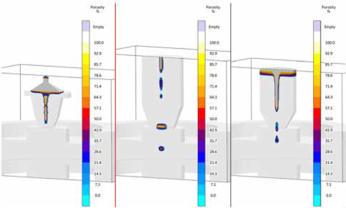
The Tele-Feeder clearly provides the correct feeder volume and modulus. It’s the most efficient of the three in the simulations performed. As expected, it provides the smallest riser and the smallest casting contact area of the three risers.
Rigging castings manually is not only relatively simple but also generates good results. Shrink defects in can be used to troubleshoot why a problem is occurring. We can also validate the results of a simulation to check our work before a new casting is put into production.
The benefits of accurate risering translates directly to foundry yield improvement, riser removal efficiency and many other benefits that lead to better results for the foundry. Chemex Tele-Feeders should be considered in any foundry where yield, efficiency and profitability are considered crucial to the success of the foundry. No matter the struggles facing the foundry, be it commercial, technical, or production, improved feeding practice will improve your foundry’s operations.